Introduction
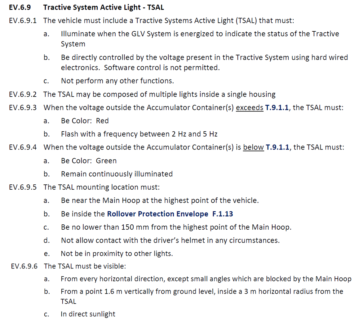
The tractive system active light (TSAL) in FSAE requires a flashing red light on top of the vehicle when the bus voltage is greater than 60V. When the voltage is below zero the light should be solid green indicating a safe state.
The TSAL must be visible in daylight from a distance, meaning fairly high powered LEDs are required. The team has an LED board designed for the top of the vehicle which requires 600mA.
Location In Vehicle
An important design factor. Traditionally QUT Motorsport placed their TSAL control board in the battery assembly on the vehicle side of the DC contactors. However, with the battery pack removed there is still a large capacitance in the vehicle at the motor controllers that could remain live for 10+ minutes if the discharge system fails. For this reason, the decision was made to place the TSAL control in the vehicle junction box, meaning the TSAL will show accurate tractive system voltage stage even with the battery pack removed.
Design Requirements
FSAE Rules 2023
TSAL Rules
Analysis of relevant rules for TSAL Control circuitry
- EV.6.9.1a - TSAL PCB must be located on the vehicle side of the accumulator, as it must always function when GLV system is energised. The GLV system is defined without the accumulator.
- EV.6.9.1b - Logic/analog circuitry must be used. No programmable microcontrollers/logic.
- EV.6.9.1c - only contain TSAL circuitry. i.e. the same threshold trigger cannot be used to trigger the voltage indicator in the accumulator for example.
- EV.6.9.3 - Output a flashing red LED signal (2-5 Hz) when the the voltage of the DC rails in the vehicle exceeds 60V
- EV.6.9.4 - Output a solid green LED signal when the voltage of the DC rails in the vehicle is below 60V
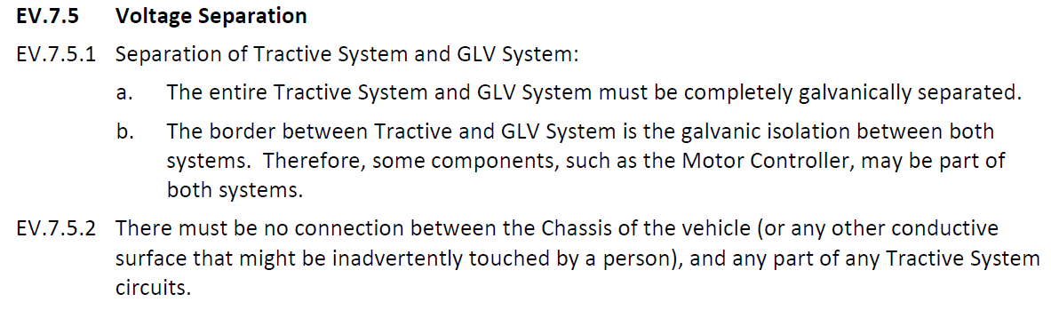
Voltage Separation
- The GLV and the Tractive circuits must be galvanically isolated
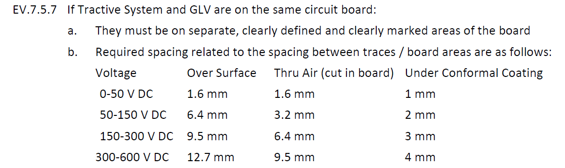
PCB Clearance
- 12.7mm clearance over uncoated surface, or 4mm clearance under conformal coating
IPC Design Requirements for TS to TS clearances
- 3mm clearance over surface for non conformal coated 600V nets
- 1.105mm clearance over surface for conformal coated 600V nets
Team Design Requirements
- The LED assembly on the roll hoop should only contain the LEDs. All drivers and control circuitry should be present on the TSAL Control board. This keeps the housing small and minimises heat and complexity in the roll hoop housing
- The LED drivers shall run on a voltage between 11V and 14.6V as the 12V LiFePO4 battery in the vehicle will power the board.
- Switch mode LED drivers should be used for their high efficiency compared to linear drivers - important with the varying GLV voltage.
- Red and green status indicators on PCB to display red/green status without external LED board connected
Design Solution

Schematics - Rev D
TSAL Control

LED Driver
