Introduction
Cell Monitoring Unit
- Talks to slave cell monitoring units (CMUs) over IsoSPI
- Filters and monitors reported cell voltages and tempeatures
- Runs cell balancing algorithm
- Interface to charger to put BMU in charge state and take commands from charger about when to pre-charge
- Has shutdown interface for Insulation Monitoring Device (IMD), precharge resistor thermal sensor (PDOC), connector interlocks, and BMU battery state. Detection for these interfaces.
Joint project with Thomas Hulbert.
Design Requirements
FSAE Rules 2023
CMU (AMS) Rules
At QUT Motorsport we refer to the ‘Accumulator Management System’ as a combination of the BMU (battery monitoring unit) and CMU (cell monitoring units)
The relevant rules from below are
- The AMS system must have galvanic isolation at every segment to segment boundary - i.e. isolation transformers
- Work in progress
IPC Design Requirements for TS to TS clearances
On surface of uncoated PCB
- 0.6mm spacing between nets >=31V potential to each other
- 0.1mm spacing for nets <= 30V potential to each other
Team Design Requirements
Revision B - QEV-3 Only
A long time solution of a ‘Revision A’ BMU strategy, using a BMU chip, a microcontroller and canbus between each slave device was used. We had some systemic issues with this which caused the upgrade.
The revision A of the CMU was designed to interface in the same position as the previous generation QEV-3 BMS system. It would feature only 10 out of 14 cells.
Assembly of this device is shown below. The pototypes were hand placed at uni and soldered in a vapour phase oven.

An implementation error with unused voltage taps was found - a fix was prototyped on the PCB as shown in the photo below.

Revision C
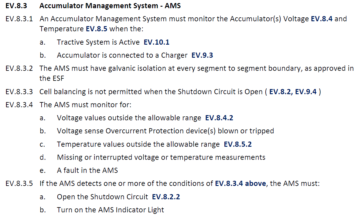
It was decided that the same CMU architecture should be used for the new vehicle - QEV-4. All 14 cells are required for QEV-4, so a 14 cell CMU should be designed and un-used cells tied together as per the datasheet.
Below shown is the full implementation of the L9963E cell monitoring unit. It was designed around a small, double sided component load form factor, enabling it to fit atop of the small QEV-4 battery assembly.
A board to board connector was chosne, enabling it to either sit atop of a carrier PCB, or, connected with a custom flat flex cable.
Prototype Assembly
Prototypes were assembled by hand and reflowed in a vapour phase oven.
Prototype testing
The initial prototypes were then thoroughly tested using a breakout board to validate cell voltage readings and temperature analog inputs.
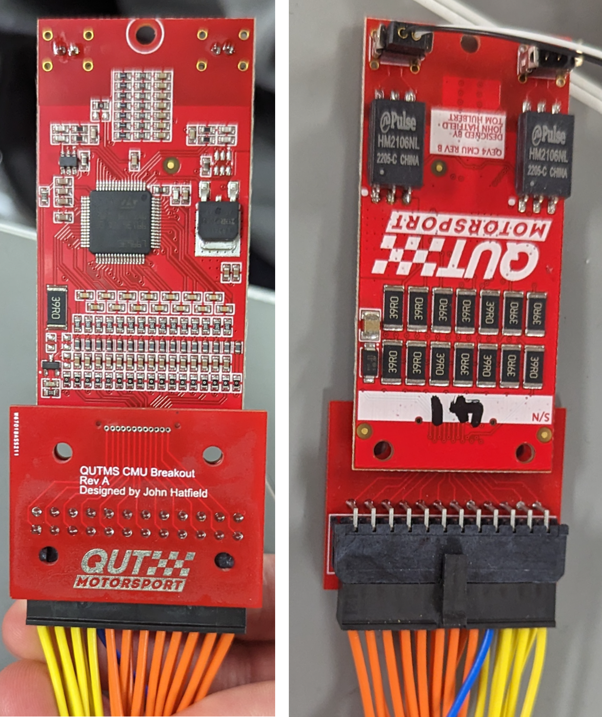
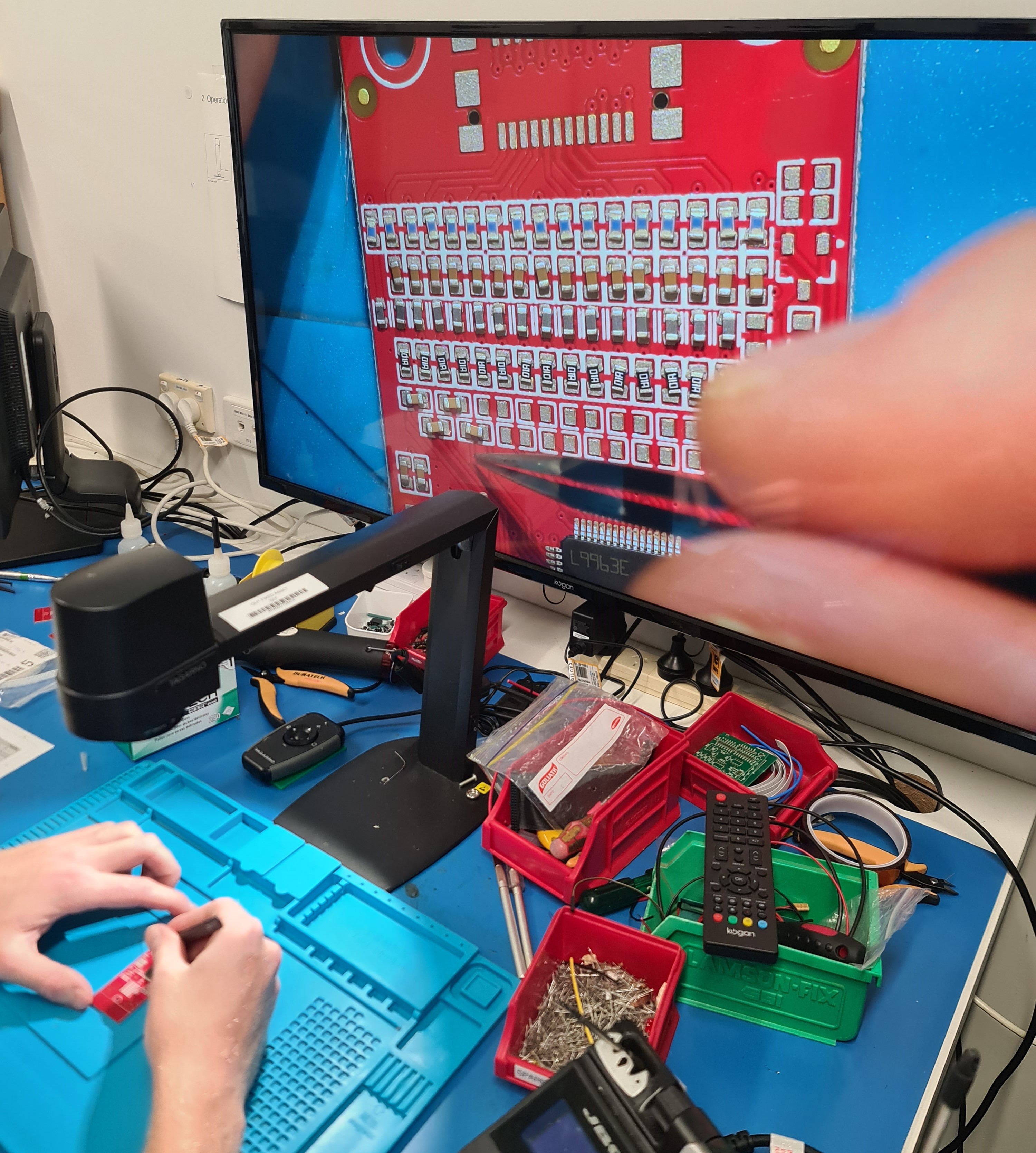
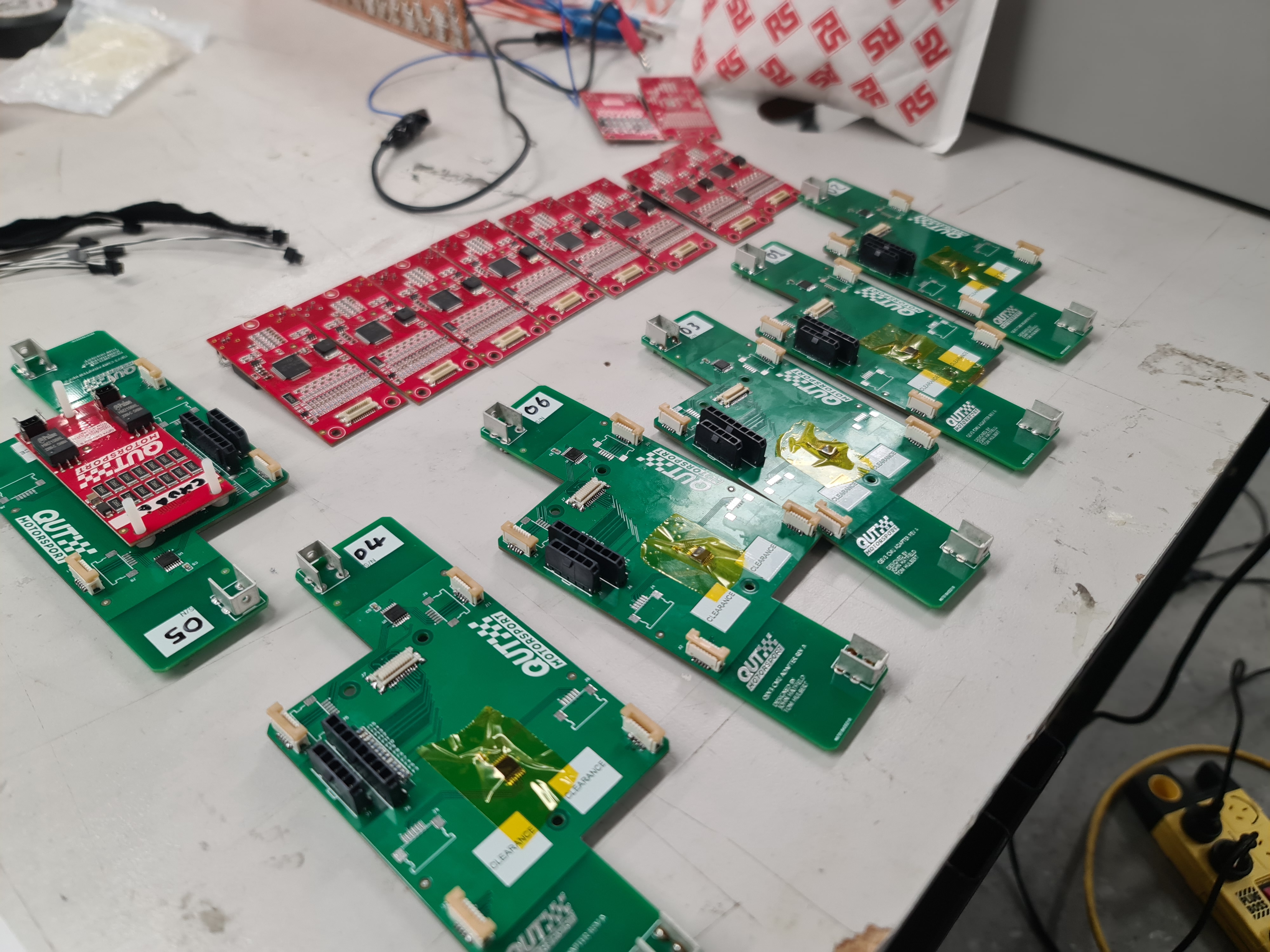
QEV-3 Adaptor
The adaptor for the previous generation car shown below connects the 10 cells, tying the remaining 4 cells together. It also has a temperature multiplexer to enable the CMU to read more tempearture cells for the larger battery assembly.
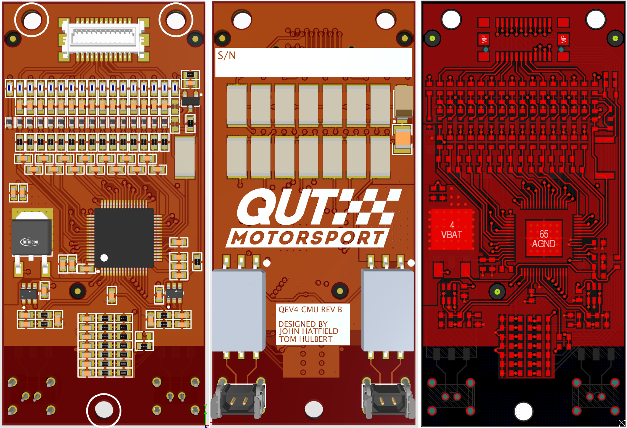
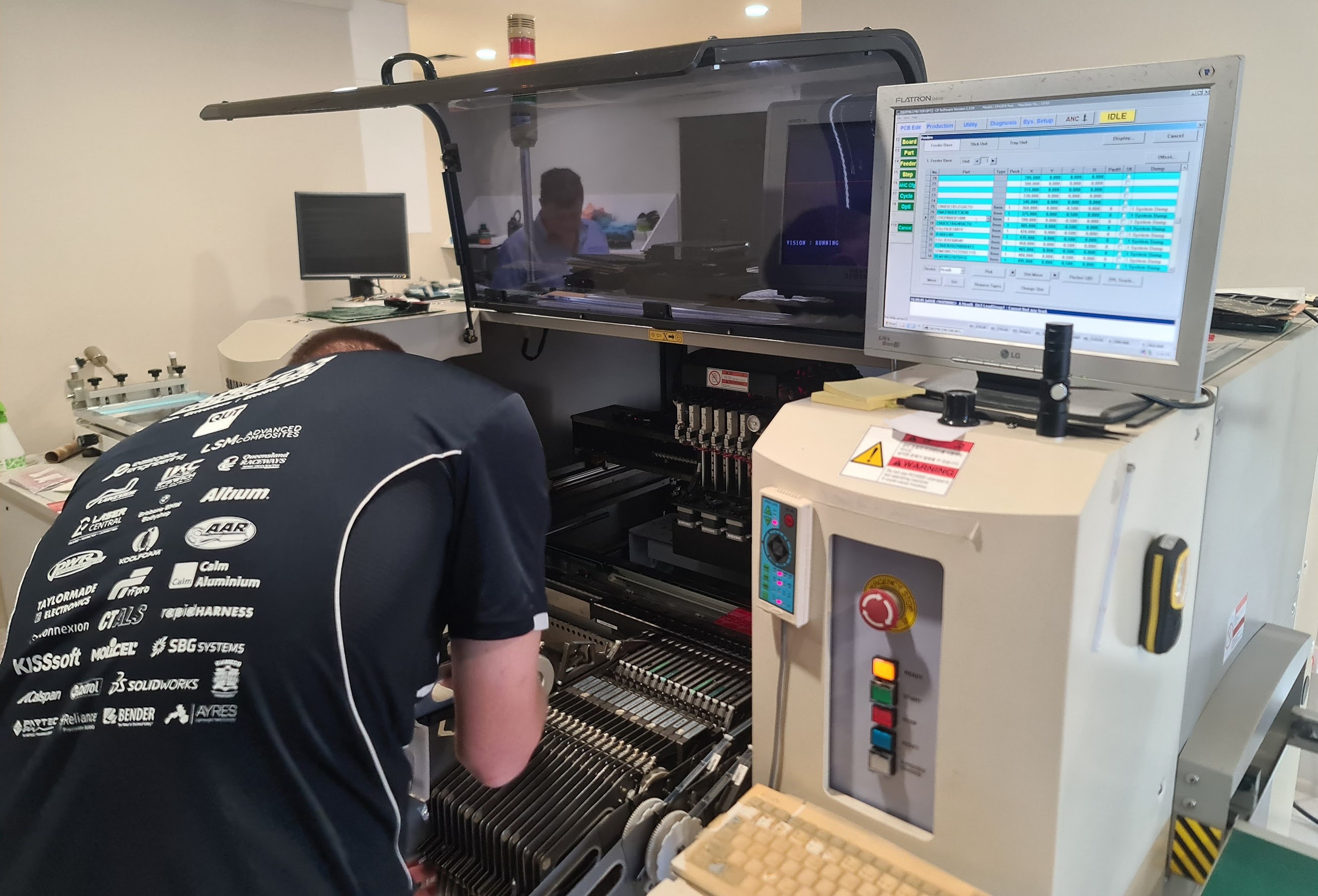
Pick and place assembly
We then worked with our pick and place sponsor, Taylormade Electronics, to pick and place enough CMU’s for QEV-3, QEV-4 and several spares. Working with Cameron from Taylormade Electronics has been an invaluable experience. It has enabled my understanding of the full design and assembly lifecycle, seeing first hand impacts of design decisions and changes on ease of assembly and reliability.
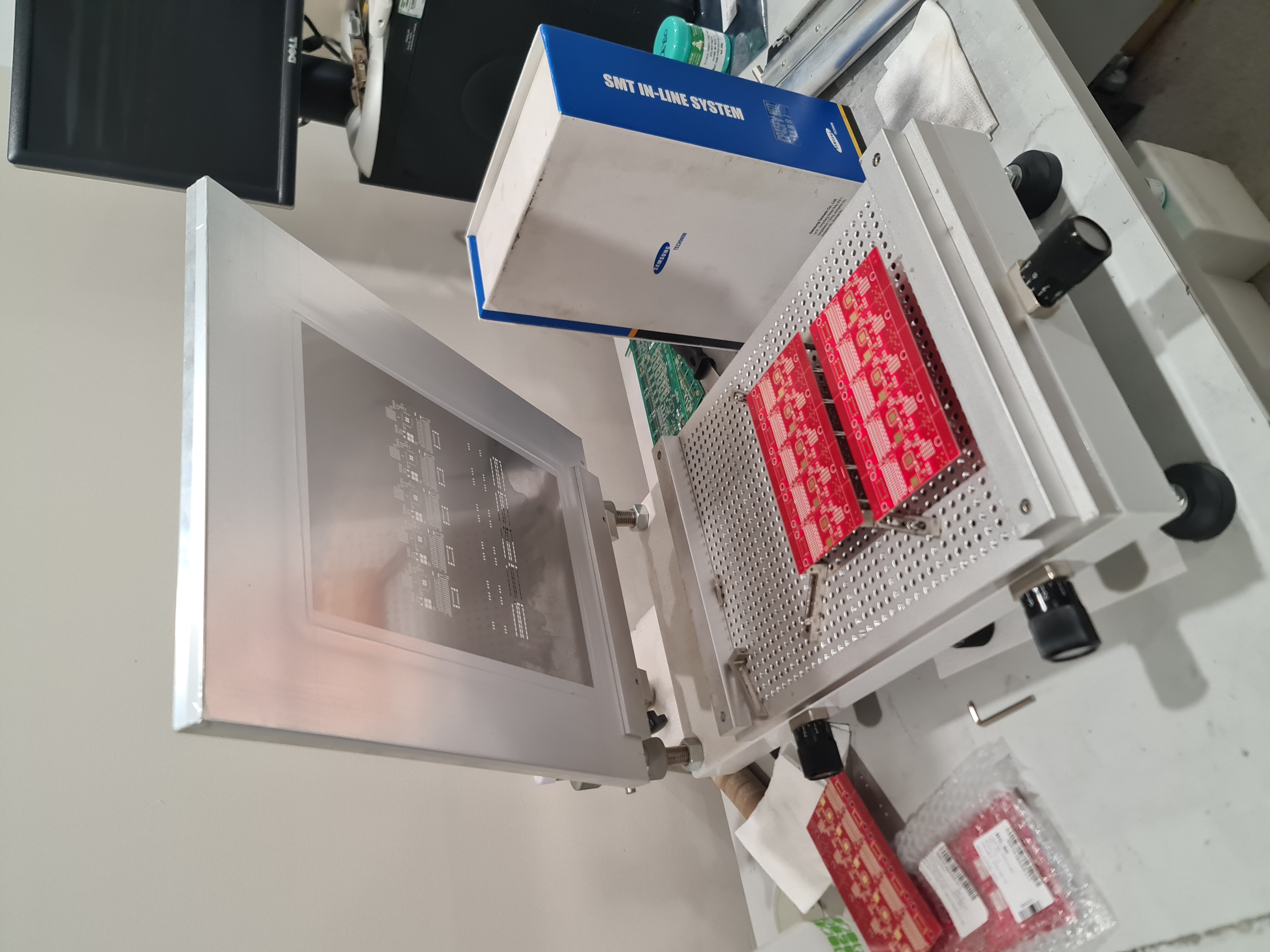
Solder Paste Application
Pick and Place Setup
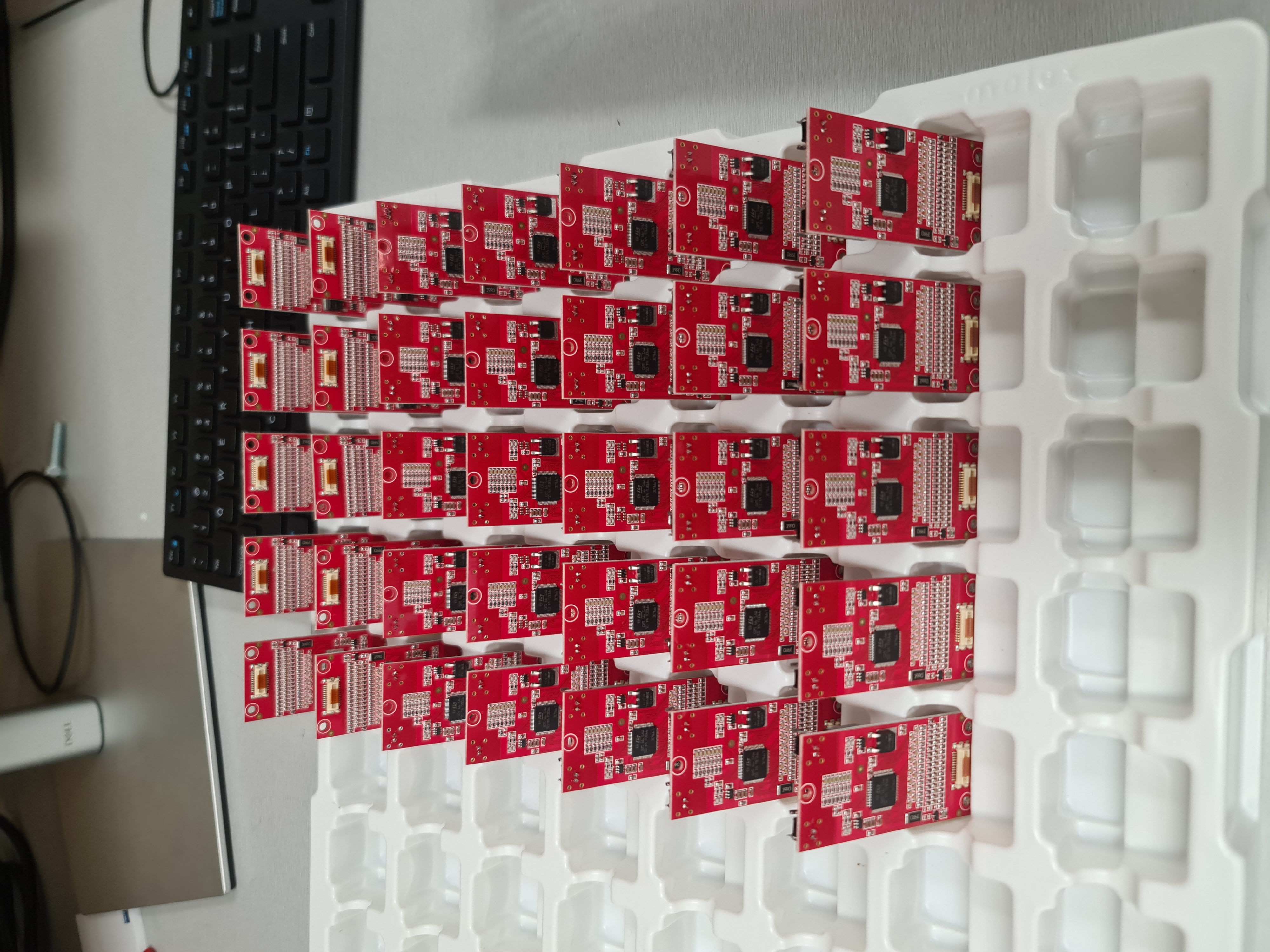
Assembled CMUs
Schematics
Not published. Please contact me for more information.