Introduction
Battery Management Unit
- Talks to slave cell monitoring units (CMUs) over IsoSPI
- Filters and monitors reported cell voltages and tempeatures
- Runs cell balancing algorithm
- Interface to charger to put BMU in charge state and take commands from charger about when to pre-charge
- Has shutdown interface for Insulation Monitoring Device (IMD), precharge resistor thermal sensor (PDOC), connector interlocks, and BMU battery state. Detection for these interfaces.
Joint project with Jarrod Fisher.
Design Requirements
FSAE Rules 2023
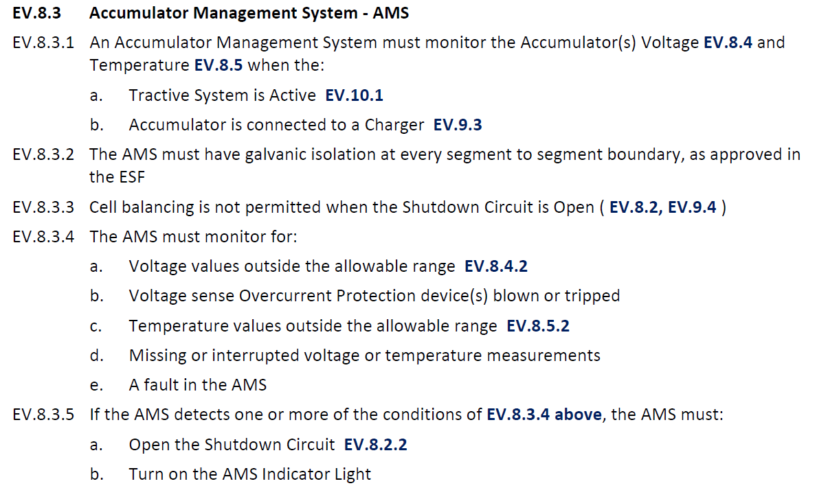
BMU (AMS) Rules
At QUT Motorsport we refer to the ‘Accumulator Management System’ as it’s industry standard term Battery Management Unit (BMU).
Some of the relevant rules are shown below, however, most of them pertain to software on the BMU, with the two core requirements from this for the BMU being
- The BMU can communicate with the cell montoring units which monitor the cell voltages
- The BMU is able to trip the shutdown circuit using a relay when there is a fault condition in software
- It must turn on an indicator light when there is a fault condition. For the revision B of this board, this should be implemented in hardware as it’s ambigious if the rules specify that you can have software implementations of the dash LEDs.
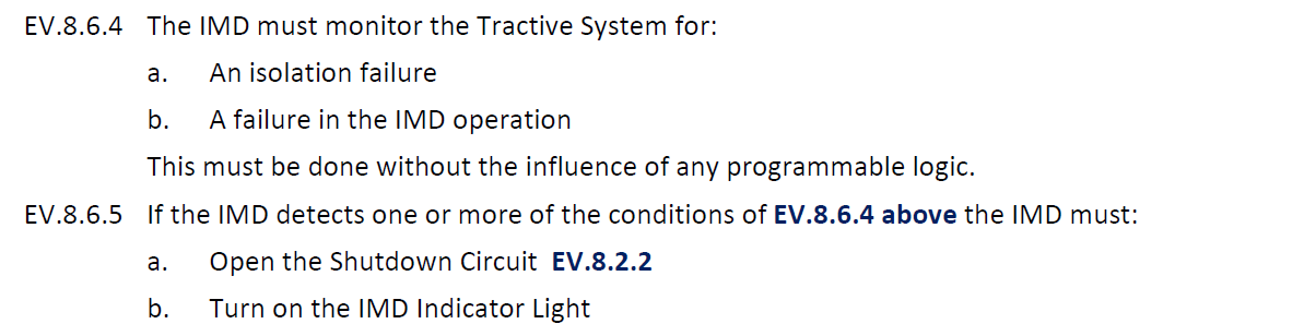
IMD Rules
The Insulation Monitoring Device (IMD) is also present in the accumulator. It has a high side 12V status signal if the measurement is good. From this we can derive the requirements
- There must be a relay present in the accumulator to trip the shutdown circuit in the event this OKhs is not high
- It must not use any programmable logic
- It must turn on an indicator light when there is a fault condition.
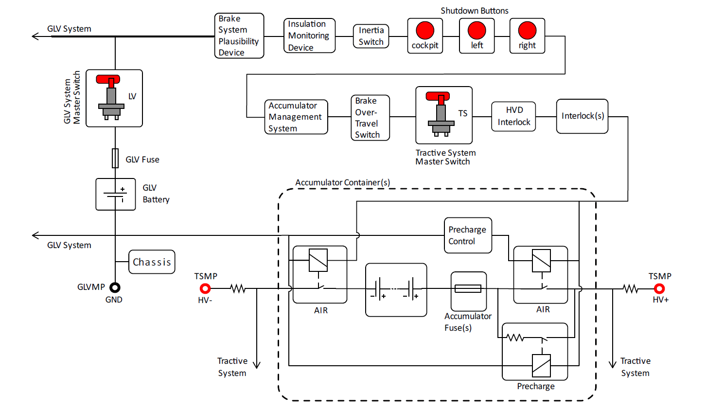
Shutdown Circuit
The output of the vehicles latched safety shutdown circuit must power the highside of the contactors. This means that if the vehicle loses power or any shutdown segment opens, then the contactors will open.
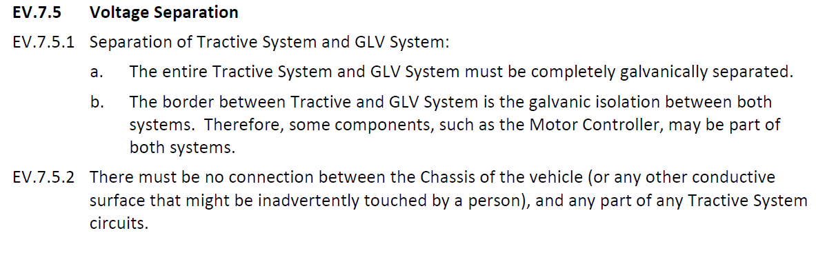
Voltage Separation
- The GLV and the Tractive circuits must be galvanically isolated
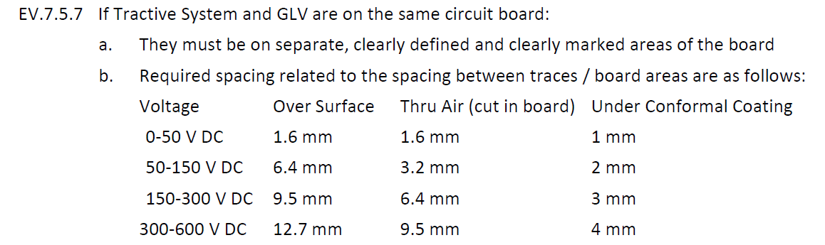
PCB Clearance
- 12.7mm clearance over uncoated surface, or 4mm clearance under conformal coating
IPC Design Requirements for TS to TS clearances
- 3mm clearance over surface for non conformal coated 600V nets
- 1.105mm clearance over surface for conformal coated 600V nets
Team Design Requirements
- Software detection of all shutdown circuits for relaying over telemetry and debugging.
- Individual control of all 3 contactors using lowside MOSFETs for ease of driving from MCU.
- One charger detection loop to detect when plugged into a charger
- E-Fuse on 12V power input - under voltage, over voltage and over current limit
- SD Card for logging of battery data and keeping state
- 2x IsoSPI interfaces to the cell monitoring unit allowing for a redundant entry point to the IsoSPI chain - L9963E
- Connector to interface all signals to IMD. This should be the IMD’s only connection to GLV.
- A connector to interface power and 2x CANbus to the Sendyne. This should be the Sendyne’s only connection to GLV.
- Use Wurth solder in standoffs so there is no compression/bending load on the PCB when mounted in the accumulator
- USB C for debugging and programming
- JTAG for debugging and programming
- 2x Indicator LEDs for status
- 2x CANbus interfaces, enabling one to be connected to the 1Mbaud vehicle bus, and the other to the Sendyne which only operates at 500Kbaud
Rev B Additional Requirements
- Latching of IMD, PDOC and BMU shutdown segments until a reset button is pushed
- Current limited highside outputs for Dash LEDs implemented with non-programmable circuitry
- Detection and measurement of the highside contactor shutdown input status so BMU can measure if operating contactors is possible
- Detection of auxiliary coils of the contactors for contactor state detection and fault measurement.
- Two charger detection loops, one for detection of plugged into charger and one for precharge start.
Design Solution - Rev A

PCB Layout - Rev A
Layer view - Ground plane layers Mid Top and Mid Bottom hidden

Schematics
Not published.
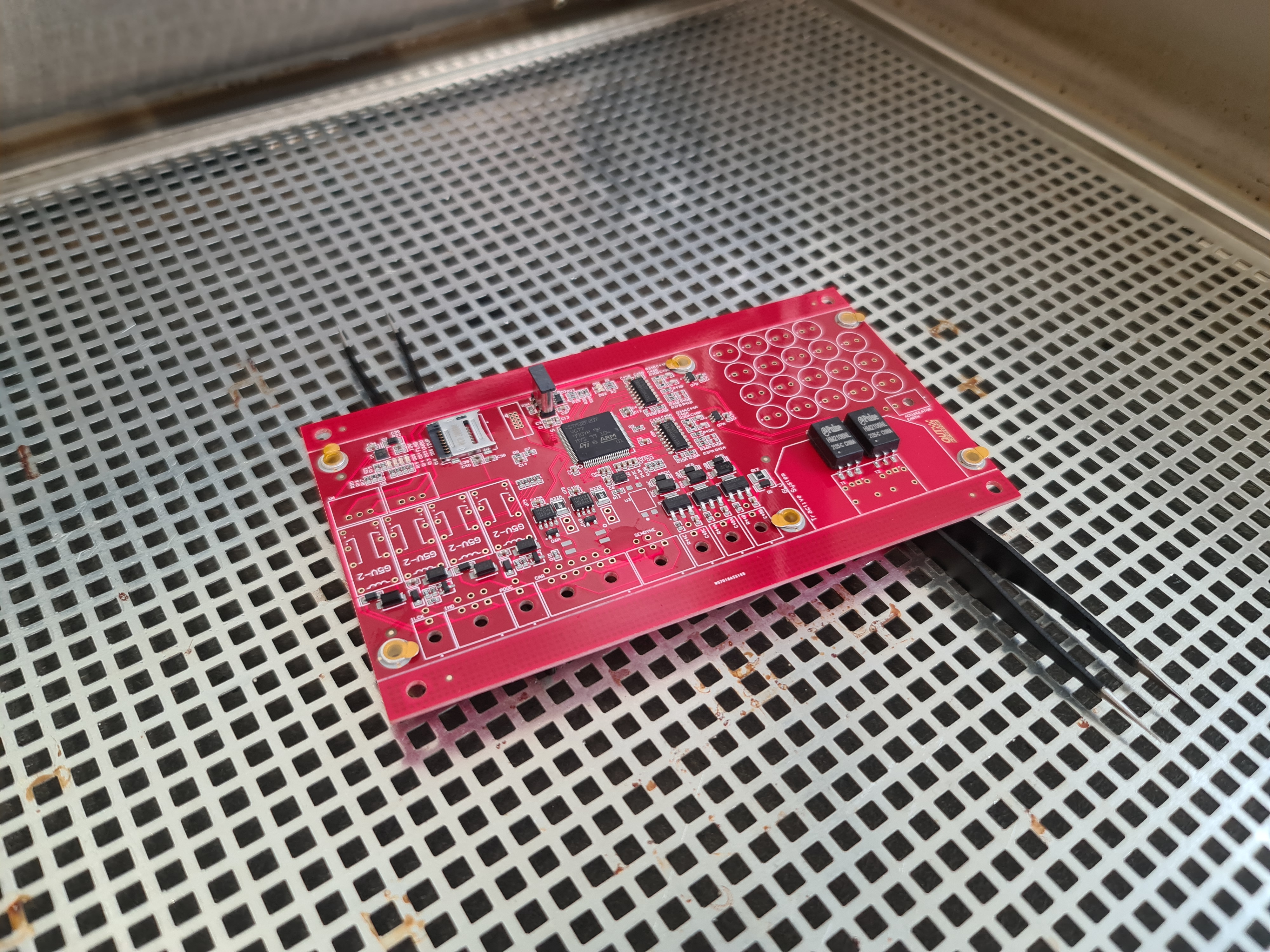
Assembly
The BMUs were hand placed and soldered in a vapour phase oven.
Rails were placed on the long edge of the PCB in the event we wanted to pick and place these as there are components close to the board edge.